Transport Vibration / Rolling Cases Rattle Internal Connectors Loose
Summary
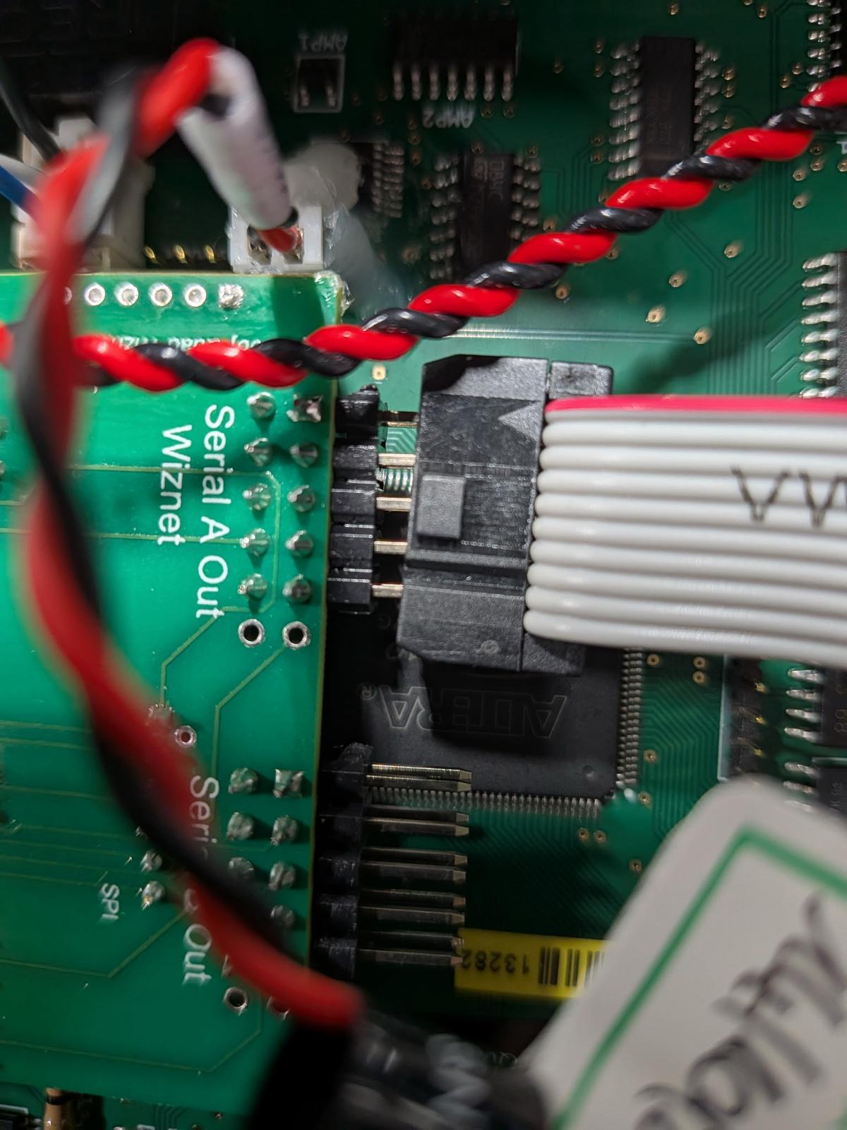
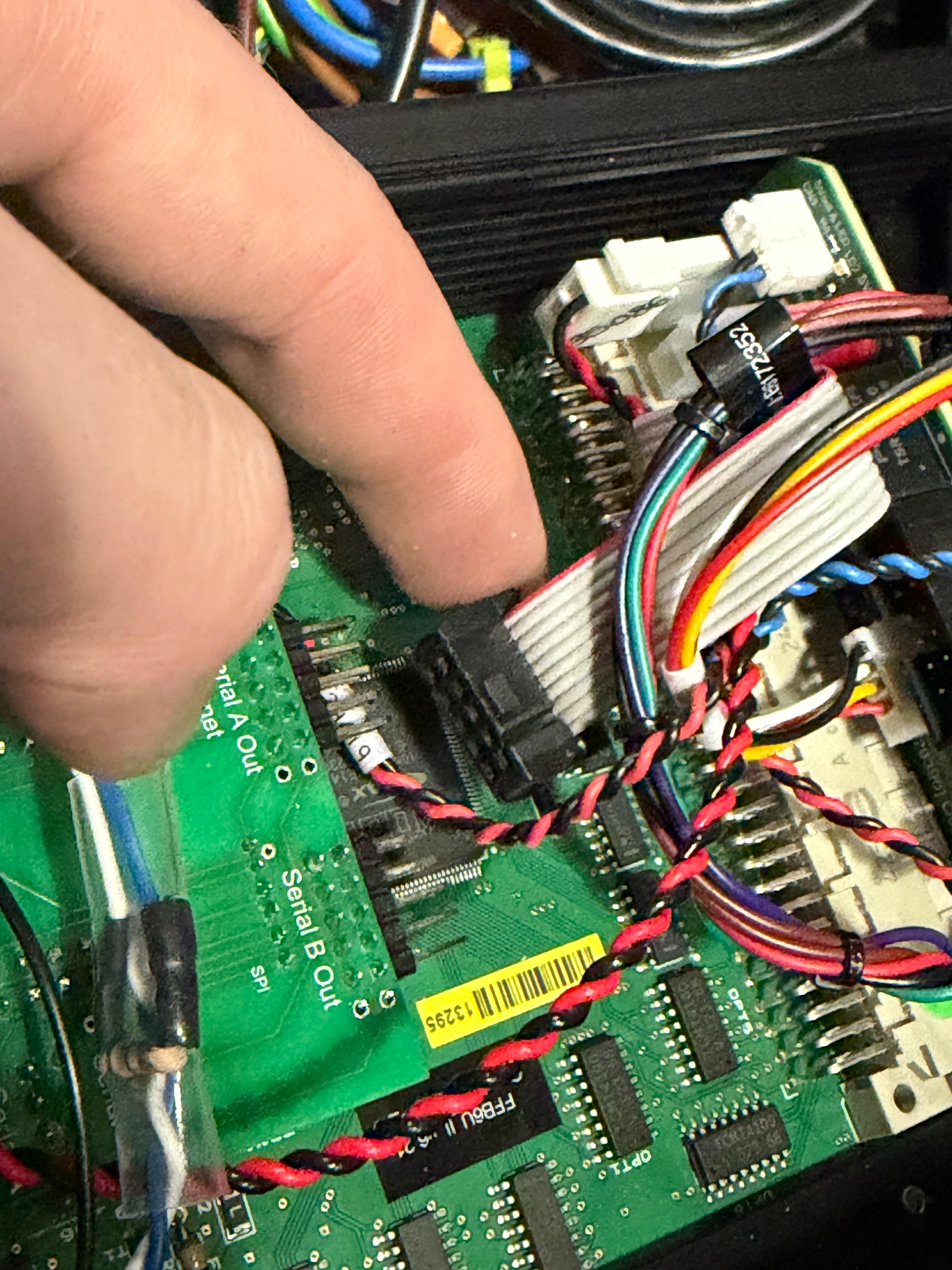
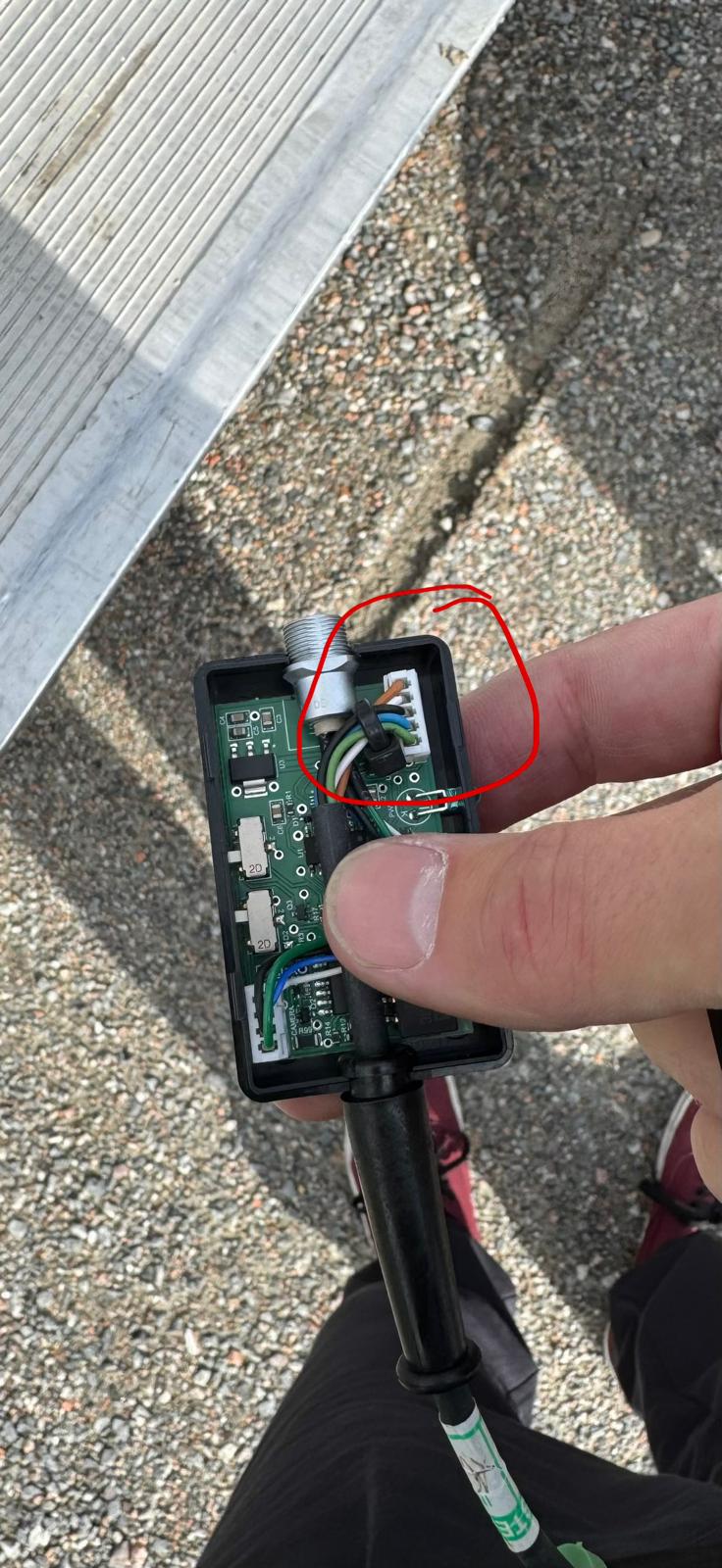
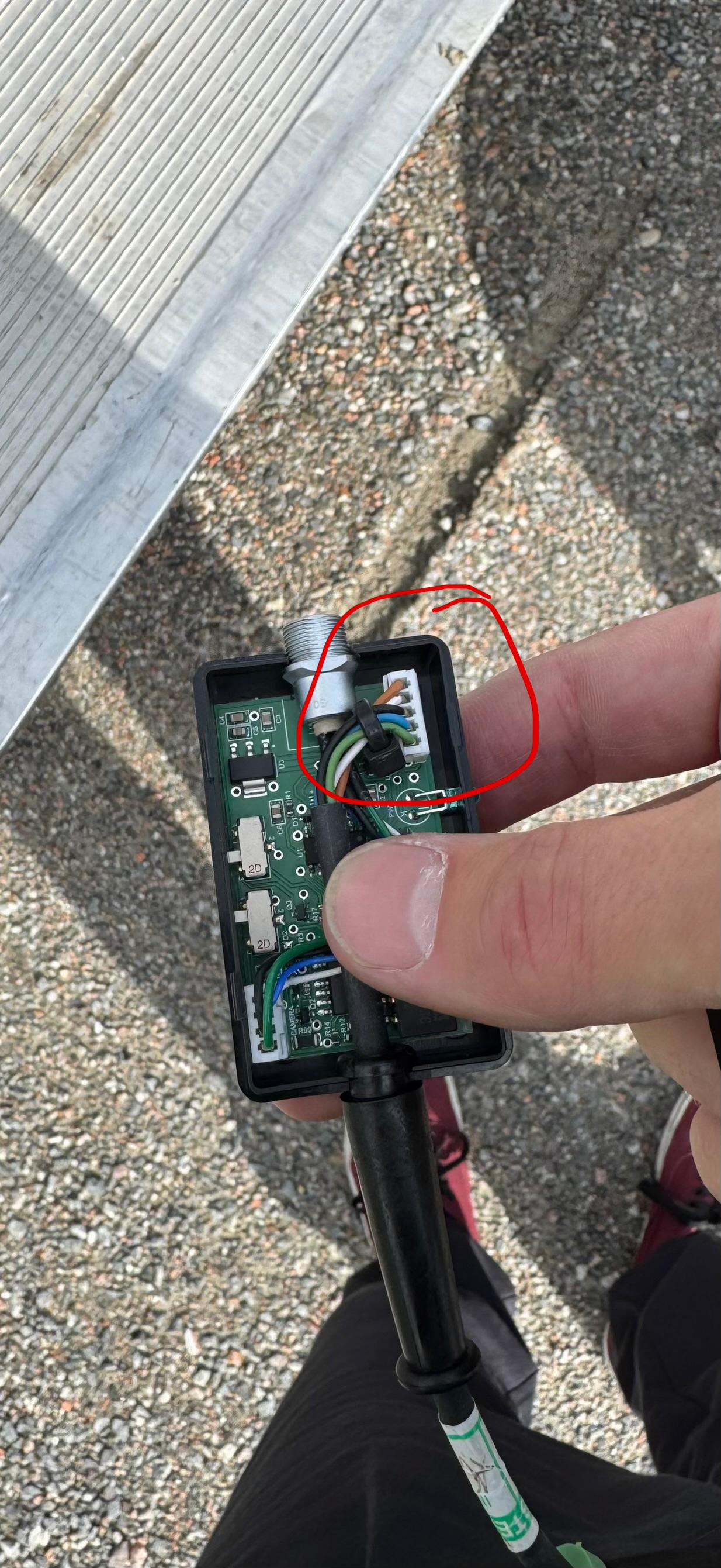
Several field reports show MRMC systems developing faults after transport, rolling controller cases, or repeated location moves because internal connectors, cards, fibre links, or small PCB headers work loose. The most explicit report was on 2026-05-18, where rolling the controller case was enough to rattle a connector loose inside the axis box in the controller case.
Treat this as a hardware false-contact family: the symptoms can look like software, network, EtherCAT, axis, sync, or E-stop faults, but the fix is often to power down, inspect, and reseat the relevant physical connector.
Power down before internal inspection
Do not reseat internal controller, CS8, axis-box, sync-box, or robot connectors while powered unless MRMC/robot support explicitly instructs you. Internal robot/controller electronics can contain hazardous voltages, delicate fibre links, and safety-chain wiring.
Symptoms
- Fault appears after transport, rolling a case, vibration, a violent move, or location move.
- System worked before transport, then fails on startup or engagement.
- Nodes disconnect, go missing, or return after cable/card movement.
- Axis trips, D/A overflow, inhibit, EtherCAT, no-engage, sync-loss, or false E-stop symptoms appear without a clear software change.
- Fault clears after reseating cables, cards, or internal connectors.
- A connector looks seated but needs an extra push.
Key Evidence
| Date / Time | User | Hardware / Area | Evidence |
|---|---|---|---|
| 2021-09-11 05:22 | Simon Wakley | CS8 / Staubli encoder path | CS8 communicates with encoders over a fibre optic link; possible causes were fibre optic contact not 100% or STARC board loose. Gordon pointed to QSG troubleshooting for reseating boards. |
| 2021-10-27 16:41 | Nitin | Track amplifier | Track/startup error resolved: "One connector on the amplifier had gotten loose." |
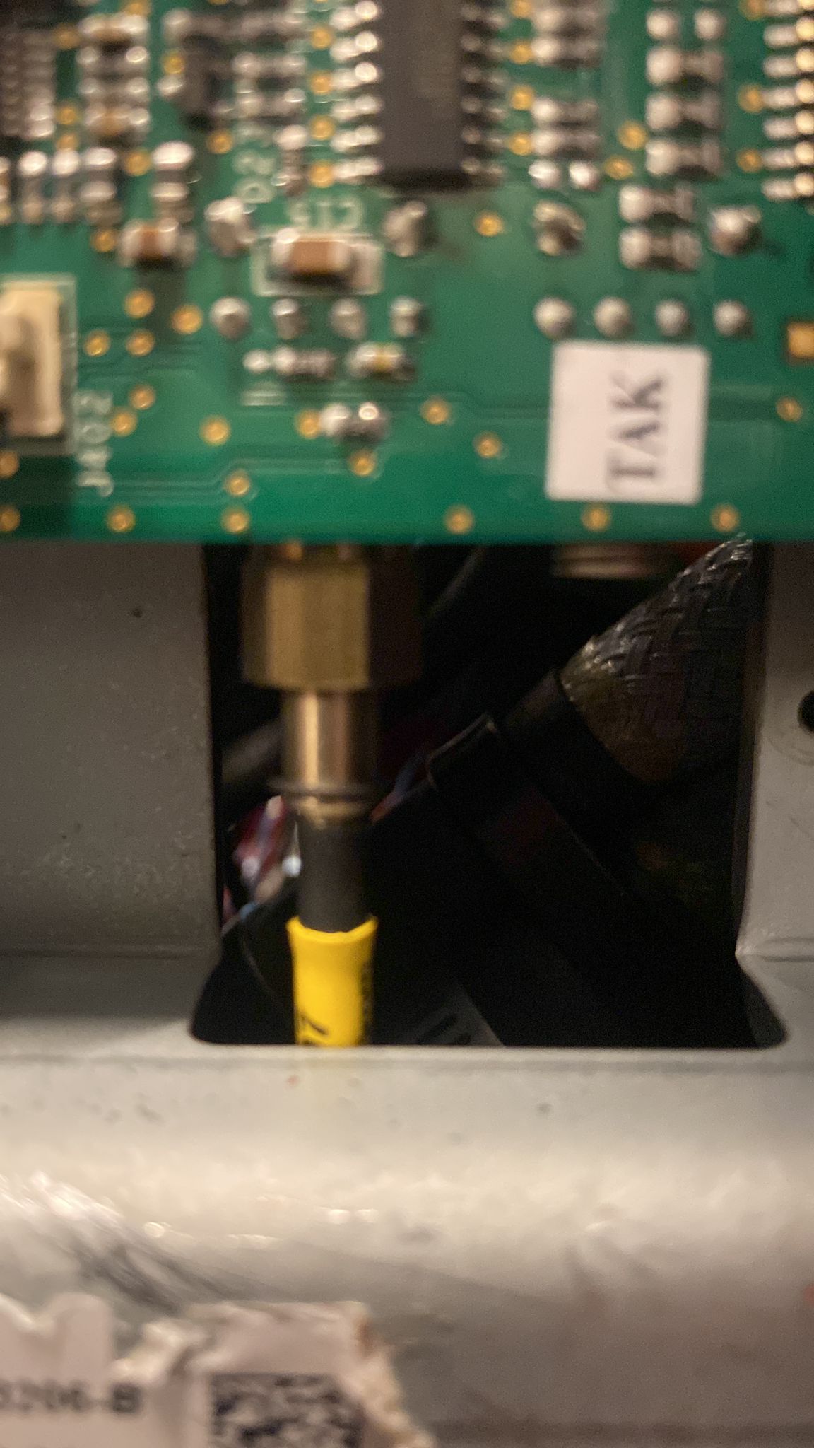
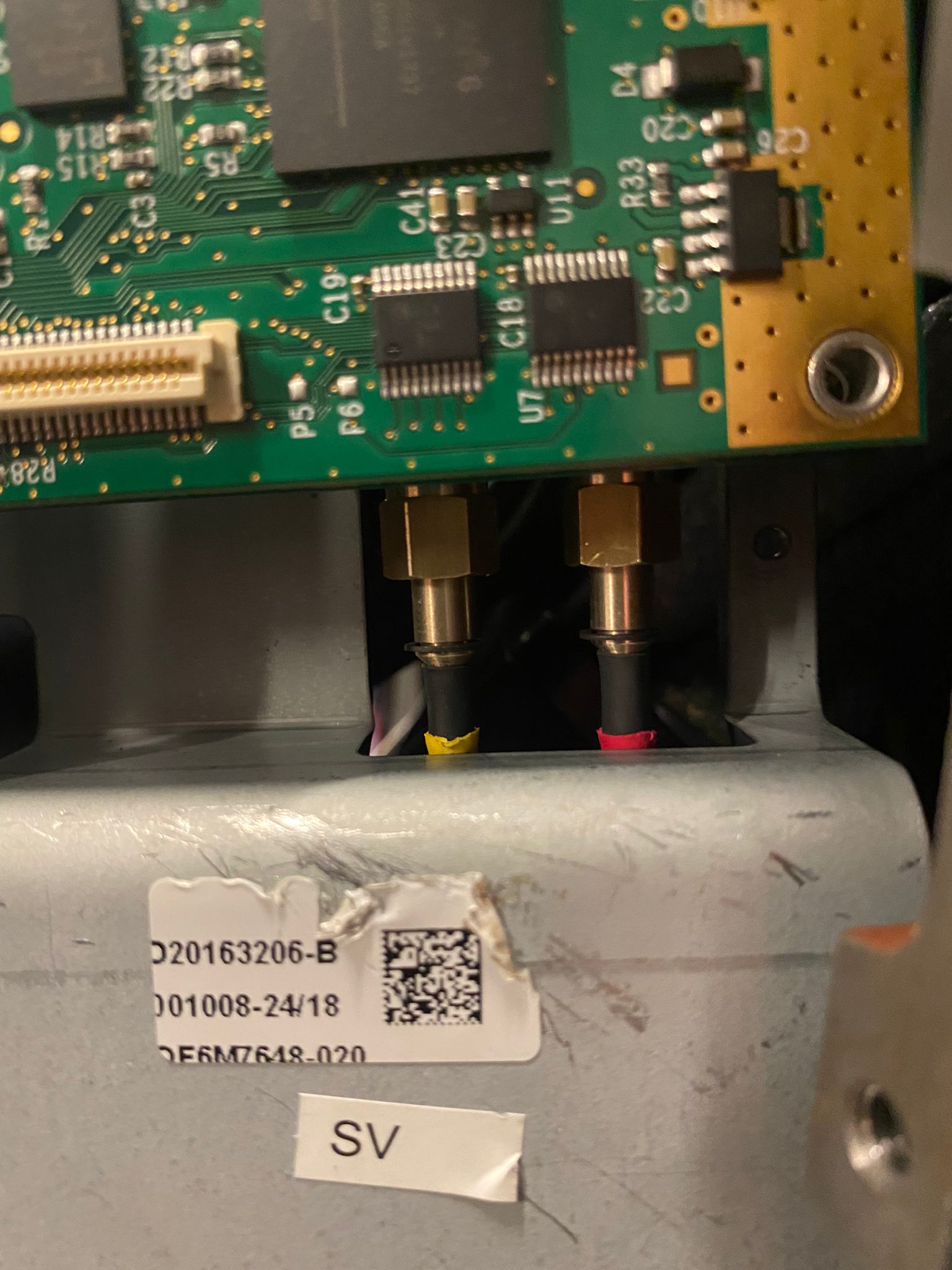
| 2021-12-03 22:03 | Dan Gottesman | Bolt / Staubli robot internal fibre | Bolt arrived after truck transport with axis-1 sensor fault; one of two fibre cables had worked completely loose inside the robot. Reconnecting it restored operation. |
| 2022-01-26 04:47 | Dan Gottesman | Track base / CS8 transport | Recommended learning the innards of the track base because several internal parts can come loose. |
| 2022-09-10 12:51 | Riley Morgan / Gordon Eschke | Staubli RX160L / CS8 | Asked about transport vibration and preventative steps; Gordon noted CS8 cards sometimes require reseating even with the retaining bracket/block. |
| 2023-03-11 18:27 | Indrek | Location transport / network | Startup fault after transport; suspected loose connectors from vibration. Confirmed fix: loose network cable. |
| 2023-08-02 01:52 | Josh Ellis-Tufts | Turntable / QuadBox cable | Turntable would not zero because a loose homing-datum pin in the turntable-to-QuadBox cable prevented datum detection. |
| 2024-01-13 02:09 | Timothy Heys Cerchio | Bolt key / operating mode warning | If key is correct but operating-mode warning remains, "connectors loose inside" was suggested. |
| 2024-06-24 22:49 | Markus | Flair 7 board test / network node | Board test error suspected as loose cable; operator planned shutdown and cable inspection. |
| 2024-07-11 06:25 | Niko | CS8 brake-release connector | Brake-release style CS8 warning could be false contact on brake-release connector. |
| 2025-10-10 19:13 | MRMC Support / Der Mo | CS8 network/EtherCAT cards | MRMC showed/supplied a retaining bracket; user still had repeat network issues that returned when moving the card from outside. |
| 2026-03-27 03:56 | Markus / Jeremy Andrews | Universal Sync Box | Images showed a five-pin connector inside sync box jumped out of place; same sync-failure thread later identified internal ribbon disconnect as one possible cause. |
| 2026-05-18 02:55 | Thomas Schroeder | Axis box in controller case | Confirmed same issue: "vibrations of rolling the case are enough to rattle that connector loose." Image/video show black ribbon/header connector partially disengaged from PCB pins. |
Related Media
Media Text / Description
- Image description: internal controller/axis-box PCB with black ribbon/header connector partly disengaged from exposed pins near labels Serial A Out and Serial B Out.
- Image description: operator finger points at a loose black header/ribbon connector inside the controller case axis box; chat says rolling-case vibration rattled the connector loose.
- Image description: Bolt internal fibre optic connector before/after reseating; one fibre cable had worked completely loose inside the robot after truck transport.
- Image description: Universal Sync Box opened; a white five-pin internal connector is highlighted/circled because it jumped out of place.
- Media 1: Image description: internal controller/axis-box PCB with black ribbon/header connector partly disengaged from exposed pins near labels Serial A Out and Serial B Out. Image description: operator finger points at a loose black header/ribbon connector inside the controller case axis box; chat says rolling-case vibration rattled the connector loose. Image description: Bolt internal fibre optic connector before/after reseating; one fibre cable had worked completely loose inside the robot after truck transport. Image description: Universal Sync Box opened; a white five-pin internal connector is highlighted/circled because it jumped out of place. Source file: 00037866-VIDEO-2026-05-18-02-55-15.mp4.
- Media 2: Image description: internal controller/axis-box PCB with black ribbon/header connector partly disengaged from exposed pins near labels Serial A Out and Serial B Out. Image description: operator finger points at a loose black header/ribbon connector inside the controller case axis box; chat says rolling-case vibration rattled the connector loose. Image description: Bolt internal fibre optic connector before/after reseating; one fibre cable had worked completely loose inside the robot after truck transport. Image description: Universal Sync Box opened; a white five-pin internal connector is highlighted/circled because it jumped out of place.
- Media 3: Image description: internal controller/axis-box PCB with black ribbon/header connector partly disengaged from exposed pins near labels Serial A Out and Serial B Out. Image description: operator finger points at a loose black header/ribbon connector inside the controller case axis box; chat says rolling-case vibration rattled the connector loose. Image description: Bolt internal fibre optic connector before/after reseating; one fibre cable had worked completely loose inside the robot after truck transport. Image description: Universal Sync Box opened; a white five-pin internal connector is highlighted/circled because it jumped out of place.
- Media 4: Image description: internal controller/axis-box PCB with black ribbon/header connector partly disengaged from exposed pins near labels Serial A Out and Serial B Out. Image description: operator finger points at a loose black header/ribbon connector inside the controller case axis box; chat says rolling-case vibration rattled the connector loose. Image description: Bolt internal fibre optic connector before/after reseating; one fibre cable had worked completely loose inside the robot after truck transport. Image description: Universal Sync Box opened; a white five-pin internal connector is highlighted/circled because it jumped out of place.
- Media 5: Image description: internal controller/axis-box PCB with black ribbon/header connector partly disengaged from exposed pins near labels Serial A Out and Serial B Out. Image description: operator finger points at a loose black header/ribbon connector inside the controller case axis box; chat says rolling-case vibration rattled the connector loose. Image description: Bolt internal fibre optic connector before/after reseating; one fibre cable had worked completely loose inside the robot after truck transport. Image description: Universal Sync Box opened; a white five-pin internal connector is highlighted/circled because it jumped out of place.
- Media 6: Image description: internal controller/axis-box PCB with black ribbon/header connector partly disengaged from exposed pins near labels Serial A Out and Serial B Out. Image description: operator finger points at a loose black header/ribbon connector inside the controller case axis box; chat says rolling-case vibration rattled the connector loose. Image description: Bolt internal fibre optic connector before/after reseating; one fibre cable had worked completely loose inside the robot after truck transport. Image description: Universal Sync Box opened; a white five-pin internal connector is highlighted/circled because it jumped out of place.
- Media 7: Image description: internal controller/axis-box PCB with black ribbon/header connector partly disengaged from exposed pins near labels Serial A Out and Serial B Out. Image description: operator finger points at a loose black header/ribbon connector inside the controller case axis box; chat says rolling-case vibration rattled the connector loose. Image description: Bolt internal fibre optic connector before/after reseating; one fibre cable had worked completely loose inside the robot after truck transport. Image description: Universal Sync Box opened; a white five-pin internal connector is highlighted/circled because it jumped out of place.
WhatsApp Excerpts
[3/12/2021, 10:04:22 pm] ~ Dan Gottesman: before (pardon the blurriness)
[3/12/2021, 10:04:33 pm] ~ Dan Gottesman: after
[3/12/2021, 10:26:07 pm] ~ Sebastian Opitz: Oh wow! Thanks for that info 🙏🏼
[27/3/2026, 3:56:06 am] ~ Markus: @~Jeremy Andrews you sure it’s not within the syncbox itself? Once our five pin jumped out of place
[27/3/2026, 3:56:08 am] ~ Markus: @~Jeremy Andrews you sure it’s not within the syncbox itself? Once our five pin jumped out of place
[27/3/2026, 4:28:22 am] ~ Arturo: How are you connecting the V-Raptor? Have you used the Sync Cable from red to the Universal Sync Box?
[27/3/2026, 5:43:33 am] ~ Dan Gottesman: hey hey - are there any rigs in Texas these days? Near Austin, in particular…
[27/3/2026, 5:44:34 am] ~ Justin Mahood: I have a bolt jr+ on track in Dallas, that can travel to Austin
[27/3/2026, 5:52:24 am] ~ Dig: Hey Jezza… I think it could be a fault with the universal sync box… The most likely is I’m sure I’ve seen it on our Milo’s… if the trigger box is plugged into the ribbon and the “camera emulator” on the trigger box is accidentally on, as soon as the sync box is plugged into the head D type, it blows the circuit.. I think the runs stop still works but the sync stops working. Is there a spare ..? Even the old style one?
[27/3/2026, 5:55:30 am] ~ Dig: Ps… the camera accessories should be connected to the ribbon on the connector labelled sync… the ribbon has two mid cable connections (one labelled sync and one labelled bloop). The end plugs into the trigger box.
Community Solutions
[CONFIRMED] Inspect and reseat the exact connector/card implicated by the symptom
Confidence: 0.86
Use the symptom to choose the first inspection point:
| Symptom | First hardware area to check |
|---|---|
| EtherCAT / CS8 encoder / axis sensor fault after transport | CS8 cards, STARC board seating, fibre optic contacts, robot-side fibre link |
| Track D/A overflow or track/startup trip | Track amplifier connector, pinch wheel cable, track base internal cabling |
| Node missing / robot not found after location move | Network cable, internal hub/switch power, base Ethernet path |
| Turntable or external axis will not zero | Datum / homing pin in the turntable-to-QuadBox / UltiBox cable |
| Sync light present but no sync reaches Flair | Universal Sync Box internal connector/ribbon and external sync cabling |
| Operating-mode / E-stop / brake-release warning with correct external state | Internal key-switch, brake-release, E-stop, bypass, or safety-chain connector |
| Zoom/focus/axis-box fault after rolling controller case | Axis box inside controller case; small ribbon/header connector shown in 2026-05-18 media |
Procedure:
- Stop and make the robot safe.
- Power down the relevant controller/box before internal inspection.
- Photograph the state before touching anything.
- Check for connectors that are visibly lifted, cocked, partially backed out, or unsupported by strain relief.
- Reseat the connector/card straight and firmly; do not bend pins.
- Check for missing retaining brackets, cable ties, foam support, or strain relief.
- Power up in the correct sequence and retest.
- If a safety-chain, CS8, robot-internal, or high-voltage connector is involved, escalate to MRMC / robot support.
[LIKELY] Add a transport checklist for known weak points
Confidence: 0.78
After each location move, rough road journey, flight case roll, or violent move:
- Inspect external robot-to-controller connectors.
- Check CS8 cards / retaining bracket status where accessible.
- Check Ethernet cables and internal switch/hub power.
- Check track pinch wheel, limit/datum sensor leads, and amplifier connectors.
- Check UltiBox/QuadBox motor, datum, and homing cables.
- Check sync-box and trigger-box cables before blaming camera settings.
- Confirm all cables have strain relief and are not hanging from the connector body.
[LIKELY] Do not glue connectors as a first-line field fix
Confidence: 0.7
The chat asked whether common loose points should be glued. The safer guidance is:
- Use designed retaining brackets/blocks where MRMC supplies them.
- Use proper strain relief, cable ties, or removable support only if it does not stress the connector.
- Do not hot-glue safety-chain, fibre, high-voltage, or robot-controller connectors without MRMC approval.
- Do not block future service access or hide an intermittent contact that should be repaired.
Official / Manual References
| Document | Reference |
|---|---|
| Bolt Quick Start Guide — p.29+: troubleshooting / board reseating context | Community pointed users to Bolt QSG troubleshooting for reseating board/card-related faults. |
| Bolt Quick Start Guide — p.41–42: network layout / internal control architecture | Useful for understanding why loose network/control connectors can look like software/network faults. |
| Trigger Box QSG — printed p.2: ribbon cable SYNC / BLOOP / TRIGGER routing | Sync/trigger ribbon routing reference for distinguishing misrouting from internal disconnects. |
Related Issues
- See also: EtherCAT "Network Communications Not Running" — Systematic Troubleshooting
- See also: Track Amplifier D/A Overflow Error
- See also: CS8 Errors After 208/240V Power Change — Loose Wires or CombiTac Connector
- See also: RED V-Raptor / Milo - Universal Sync Box Failure and Misconnection Risk
- See also: Cinebot Mini Rotate Axis Trips — Robot-to-Controller Connector / UR Support File
- See also: Bolt X Network Error Persists After Cable/Hub/PC Swap — Unstable Base Ethernet Port
- See also: Bloop Light Laser Pointer Faint or Not Working